
You have already seen acronyms OVH, (S)OVHC, DOVHC, DAS, RAS but never knew what it meant? This article will bring you some informations about the engine designs, and their engineering systems.
Understand their need throught thermodynamics
A 4 strokes engine requires a timing combination of fluid flows to run. The petrol engine theorically follows the Otto cycle thermodynamic law, divided in several steps (fig.1):
- 0-1 The intake phase : The combustion chamber expands to allow the fuel mixture to take place.
- 1-2 The compression phase : The combustion chamber is shrinked to increase the thermodynamical efficiency.
- 2-3 The heat phase : The temperature in the combustion chamber increases due to the fuel mixture ignition and combustion. As a result, the pressure increases.
- 3-4 The expansion phase : Due to the pressure increase in the combustion chamber, this energy will be used to be converted into work and the combustion chamber will expand.
- 4-1 The cooling phase : The heat is extracted from the combustion chamber. The pressure drops.
- 1-0 The exhaust phase : Burnt fluids are extracted from the combustion chamber, to leave space for a new fresh fuel mixture.
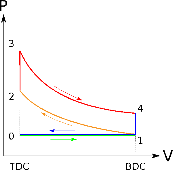
From those 6 phases described, a volume variation is observed only 4 times. These 4 times correspond to the 4 strokes of a thermal engine. Due to the engine architectures, the combustion chamber volume constantly variates due to the piston movement. Hence, the heat phase and the cooling phase occur during these volume variations.
Poppet valves introduction
After this small theorical lesson about thermodynamics, we better understand the importance of fluid flows in the petrol engine running. To perform the various fluids exhanges with the surrounding environment of the combustion chamber and ensure perfect sealing at some specific times, a new part system is now required. Since the beginning of 4 strokes petrol engines, the use of poppet valves has been introduced and widely used for this application (fig. 2).
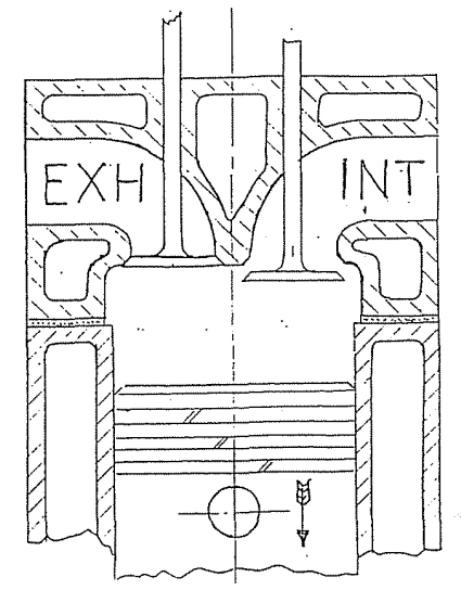
Poppet valves or more commonly called engine valves, are made of a stem linked to a head. This head has a shape of mushroom and rests on a seat insert to ensure a good combustion chamber sealing. One side of the valve is in contact with the combustion chamber and the other one with cylinder head ports where the fluids are intaked or extracted from the combustion chamber. The kinetics of the poppet valve is linear thanks to the stem guidance.
The valve train concept
Historically to ensure the valve movement, two different parts systems has been used. From one side, a cam system pushes the valve to assure its opening whereas a spring recalls it to recover the combustion chamber sealing (fig. 3). If the valve spring almost always surrounds the valve in the cylinder head, the camshaft location can vary from one engine to an other. As a consequence, depending on the camshaft location and the cam drive, different parts systems can take place in between the valve tip and the camshaft. This architecture defines the valve train design.

First, we can define two main families of valve train depending on the camshaft location. The first architecture has shown the camshaft to be located in the crankcase. This is called the cam-in-block layout. The camshaft is located near by the cranskshaft in the crankcase, and is driven by a chain, or a set of gears. The valves can be located either in the block : the flathead as in fig. 4 (also alled valve in block engines), or overhead in the cylinder head. The former design has been replaced by the overhead architecture, as it led to better fluid exchange performance (fig. 5). The reverse movement is allowed thanks to a inversion motion mechanism : a pushrod is transmitting the force to a rocker while rotating around an axle, from its center.

The second family of valve train architecture deals with overhead camshaft (OHC). On such engines, the camshaft is located in the cylinder head and is driven by a belt, a chain or in some rare cases, by a gear train (on some ferrari models).
The major drawbacks of the cam-in block architecture are a bad performance fluids flow (with the flathead design) or a high heavy valve train du to the combination of various parts in the valve actuation (with OHV design). At high speed, this mass is very not desirable as it is power consuming. Due to the high requirements in engine performance and consumption requirements, the cam-in block design has been replaced by the overhead camshaft design (OHC). By now, the camshaft is located in the cylinder head, and not in the lower cranskcase anymore which helps to reduce the distance between the camshaft and the valve, by conserving valves over head (OHV architecture) which is favorable for the fluids flow. As the axle distance increased between the lower crankshaft and the upper camshaft, a belt or a chain system is commonly used to drive the cam pulley.

The use of the camshaft in the cylinder head allowed the emergence of multiple mechanisms to lift the valves. The first one is the direct acting system (fig. 6). The camshaft is located above the valve, and a cam follower receives the linear movement of the cam lobe to transmit it to the valve tip. The second one is the rcoker arm system (RAS in fig. 7). As presented in the cam-in-block architecture, the rocker is rotating around a fixed axle, but receives the movement from the cam throught a tappet, a roller or a direct contact with the cam lobe.

The last valve train configuration is the last one introduced in automotive industry. The rocker is not used anymore, and leaves space to a lash adjuster whichs plays a similar role as the rocker (fig. 8). However, the lash adjuster is not guided anymore around a fixed shaft but around a ball joint adjusted in height. This allows to accomodate for perfect valve clearance. The height can be adjusted throught a screwed system, or an hydraulic tappet (automatic play regulation). This system allow to lighter the moving parts as the adjustement part which gives additional wheight is now fixed, in opposition to the rocker arm systems.
